Friday, 13 May 2011

Medieval toolchest: Hammers and mallets


The hammer and mallet are both tools for hitting /striking others instruments. The hammer has an iron head, while the mallet is made completely of wood.

The medieval hammer used in carpentry is most often seen as a claw hammer, sometimes reinforced with long metal strips along the handle. The hammer is used for striking nails and dowels into the wood. A specialised form is used for closing rivets (riveting hammer). Metal hammers are common finds, but it can be difficult to assign the tool to a specific trade, as also smiths, stone cutters, shipwrights, among others, used hammers. 

 
A 15th century claw-hammer. Image from 'Das Werkzeug des Schreiners und Drechslers' by Gunther Heine.
A clawhammer with a reinforced head and a wooden mallet from the Bedford Hours miniature 
'Building the arc of Noah', 1433, London, British museum, Ms. 18850.

A riveting hammer in the right panel of the Merode Altar by Robert Campin, Metroploitan Museum of Art, New York.

The iron head of our medieval clawhammer is made by Deagrad. The handle is homemade from ash and secured with an wooden wedge. Ash is often used for handles as it has some flexibility


The mallet is used to secure pegs (for instance for the pole lathe), hitting chisels and gouges, hitting the holdfast, wedges and benchdogs. Medieval mallets were constructed either as a square or round block attached to a handle and as (turned) cylinders in the length of the handle. 
The first type of mallet hits with the hard endgrain, and can be used with more force. Large versions of these hammers were used with wedges to split wood into planks or smaller pieces (see images below). A smaller square mallet is shown in another miniature below..Many hammers of this type with a round head are found in the miniature of Noah building the ark in the Bedford hours (see image above).  

A woodcutter (Virich Holzhacker) from the Mendelschen Hausbuch (around 1414) uses wedges and a large mallet to split wood.
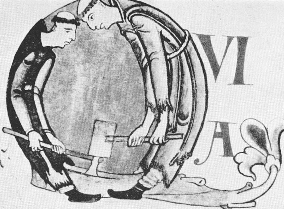
 
Two monks are slitting wood with an axe and a large mallet. 12th century miniature from St. Gregorii Magni Moralia in Job. Dijon, City library hs. 170, fol. 5970.


 Eve uses a mallet and chisel and Adam a breast-auger. 
12th century miniature from Homelie de St. Basile.

The cylinder type of  mallet construction ensures that a chisel always is hit evenly with the mallet, whatever manner it is hold. However it hits with the long grain, which is more easily indented. Thus pictures often show these mallets with the cylinder hollowed out, i.e. the very worn out ones. This type is found for instance  in another image of the Mendelschen Hausbuch shown below.

A cylindrical mallet used by a medieval joiner (Peter Screiner). Mendelschen Hausbuch  around 1444.
 A 10th century wooden mallet found in the Coppergate deposit in York, UK (no. 8188). The head is willow with a hazel handle. (Image from C.A. Morris - Wood and woodworking in Anglo-Scandinavian and medieval York)

We have two types of mallets in our toolchest, a square one (oak hammer head with an ash handle), and two turned cylinders made of acacia. (I recently discovered that this is an exotic tree; the first acacia was planted in Europe in 1579 in Castle Doorwerth, the Netherlands, so we will have to replace these mallets in time with ones made of correct wood). The tools are finished with linseed oil.  


Monday, 9 May 2011

The footrest for the strycsitten

This is the final part of the making of a medieval strycsitten and deals with the construction of the footrest. The footrest is not strictly necessary, but is shown in many of the paintings (see my post on the strycsitten of 7 January 2011). It is also a useful piece of furniture in medieval times - it keeps your feet of the cold (stone) floor. Therefore, in my view, it forms an essential part of a medieval strycsitten.

The footrest is usually slightly longer than the strycsitten. The legs of the footrest fall inside the legs of the strycsitten (this means you have to mind where you place your feet if you stand on the footrest!). The footrest is a separate and movable piece of the strycsitten, i.e. when you change the position of the backrest, you move the footrest to the other side of the strycsitten as well. With this in mind, I made the plan of the footrest completely symmetrical as shown below with the form of the footrest legs.


Plan of the footrest legs. The form is more or less similar to the legs of my "Savonarola" X-chair (see next photo).

The savonarola chair: the legs have similar roundings.

The plank of the footrest was planed to the same thickness as the seating of the strycsitten and rounded off at the edges. The legs were roughly sawn using a band-saw and then finished by hand with a chisel. Also the tenon was cut out using a chisel. I used the tenons to mark the mortises in the footplank, which were cut out as well. The three legs were attached to the plank with two small (6 mm) dowels through each mortise and tenon joint.

Four legs of the footrest; one is a spare. The tenon is not yet cut out.


The still square footplank attached to the legs for testing the fit of the mortise and tenon joints.


The leg with the mortise and tenon joint.

The mortise and tenon joint shown from above.
The joint fixed with a dowel.

The complete footrest.


A footnote for the footrest:
Now, in modern times, the footrest proved to be a nuisance. The strycsitten is part of our dinner table seating and we kept stumbling against it. Besides, with our modern flooring we do not suffer from cold feet, so the functionality is lost as well. The footrest now occasionally appears in the living room to show the complete set.

Tuesday, 19 April 2011

Constructing the oak strycsitten

This post continues the tale of the making of the strycsitten. After the test with the pine model and carving the oak panels and 'traingle' supports I continued by making the frame of the strycsitten in European oak. This is rather straightforward work: oak beams are planed to their appropriate thickness; mortises are cut using a mortising tool and the corresponding tenons sawn by hand.

Using the mortising tool in the workshop

The next step is to cut the grooves for the support triangles and the panels. The main work here was done with a router table and finished by hand with chisel and router plane. Then the holes for the dowels (for the mortise and tenon joints) were drilled. These holes are slightly smaller (5.9 mm) than the dowels (6.0 mm) to provide a tight fit. Furthermore the dowel-hole is first drilled in the frame but without the tenon in it. The tenon dowel-hole in is drilled separately and slightly closer (~1 mm) to pull the two parts of the frame together (see image below).


When all dowel-holes were drilled, the panels and triangles were fitted in the grooves and everything was fixed by hammering in the dowels.The frame was then finished with three layers of linseed oil.


After the frame was completed the seating board had to be added.  The seating was made of two oak boards which were connected with a loose tongue and groove joint. As wood works, the loose tongue and groove joint allows the seating boards to expand to the middle. The seating boards were finished with linseed oil before they were fixed to the frame at one end with a dowel.

 In each corner a dowel was used to fix the seating board to the frame. 
This restricted the wood to expand to the outside, but allowed it to expand to the middle of the seating.

 The loose tongue and groove joint was wide enough to allow for expansion of the seating boards (small double arrow). There is also space around the middle style (shown by the two long arrows).
 
Next, the backrest of the strycsitten was made. The backrest consists of a square beam, which is chamfered at 45 degrees in two of the corners along the length of the beam. This removes the square edge which would otherwise point in your back. The large chamfer makes the backrest really comfortable to rest against. The backrest was secured to the arm parts of the backrest with two dowels. The completed backrest was finished with three layers of linseed oil before at was attached to the strycsitten.

 The completed backrest - the same size as our modern sofa. 
The hole for the turning point can be seen in the arm part of the backrest.
Detail of the backrest. Two dowels secure the parts of the backrest. 
Note that the chamfering is not done at the backside. 

Finally, the completed backrest was attached to the armrests of the strycsitten. I used a 12 mm wooden dowel with wooden buttons as the turning point for the backrest. An iron rod is often used for strycsittens as a turning point (e.g in the strycsitten of the Rijksmuseum Amsterdam or the Loevesteijn replica). I did not want to use iron: it reacts with oak, I would have needed a blacksmith to make it, and a wooden is strong enough and can easily be replaced if necessary. The wooden buttons were made with a tenon cutter, the button-hole was drilled using a forstner bit and the button was rounded with a belt sander. Attaching the wooden buttons to the dowel was the only point in the construction where glue was used. However, I used a skin-based glue, which was also available to the medieval woodworker.


 Dowels used for securing the mortise and tenons, and the turning point dowel with the oak buttons.


 The turning point dowel attaching the backrest to the frame of the strycsitten.

The strycsitten itself was already finished early in February. Only one part remained to be done (which is also finished now): the footrest. However this will be the subject of another post. Two images of our completed strycsitten are shown below.

The completed strycsitten - with footrest.


Tuesday, 29 March 2011

Nürnberger Hausbücher

Perhaps this is already known for quit a while, but it was new(s) for me. When I was searching internet for  medieval miniatures with woodworking subjects and furniture items, I stumbled upon the complete "Hausbücher of the Mendelschen and Landauer Nürnberger Zwölfbrüderstiftungen. These books date from 1425 into the 1800's and depict the brothers applying their former trade at the time they died. The books are a great resource for any re-enactor, as they show all kinds of trades with their specific tools  at a clearly defined time period. For the Saint Thomasguild the medieval turner Lienhard Drechßel (image below) and joiners Karl Schreyner (right) and Peter Sreiner (left) of around 1425 are the most interesting, but also the  images of carpenters, sawyers, coopers and wheelwrights show parts of the woodworking trade.


The Hausbücher of the Nürnberger Zwölfbrüderstiftungen can be found at www.nuernberger-hausbuecher.de and are searchable on professions (e.g. joiner), occupation categories (e.g. woodworking), tools (e.g. axe), materials (e.g. wood), products (e.g. furniture) as well as the disease the craftsman died off (e.g. dementia). The site is mainly in German, but can be searched in English as well. The images in this post are derived from this great site.


Sunday, 13 March 2011

Medieval furniture in Gammla Uppsala church

Today I was looking through my book of old furniture projects and came across a set of postcards from my holiday in Sweden in 2007. We stayed in Uppsala for a week and visited the old parish church of Gammla Uppsala. The small church actually consists of the remains of the bishopric cathedral, which was destroyed by fire in 1240 (the bishopric seat moved to the new Uppsala). Inside the church are two medieval chests and a medieval turned seat. I tried to make clear to the verger, who did not speak English, that I wanted to take photos. In the end, he understood and agreed. The results are shared in this post.


  Gammla Uppsala parish church / old cathedral.


Iron bound dugout chest, 12th century, in use as an alms chest.


Turned bishopric throne, 12th century (postcard).


The small turned vertical rails are in two different colours.

14th century carved chest (postcard).


The same chest. One of the foot rails is missing. 

You can see the place where the original lock plate used to be. The current hinge is not the original.

  The side of the medieval chest.

A look at the backside of the chest.


The lid of the 14th century chest with modern church paraphernalia. 
The hinge extends to the back of the chest.

Wednesday, 9 March 2011

Carving oak panels for the strycsitten

The panels and the supporting 'triangles' for the horizontal rails are the most complicated parts of the strycsitten as they are ornamented on both sides. They were made of  European oak. I used a combination of modern machinery (drill press, router) and traditional hand tools (gouges, chisels and chip knife) to make the  four panels and eight supporting triangles.


Panels

The panel were made of simple oak planks slightly smaller (3-4 mm) than the grooved frame they  had to be inserted in, allowing for shrinking and swelling of the wood. Below the decoration plan of the panels is shown (left). On the other side (right) an alternative plan I considered but did not use is shown.


A pine panel to test the thickness of the chamfered edges and the depth of the lowered parts.

I started drilling the holes using a drill press with Forstner bits. This allowed for an exact and smooth cut. After that the 'windows' were rougly cut out using a jigsaw. I continued  making the 'windows' identical using a jig with a router. After that another jig and router was used to lower the circle with the three drilled holes. I carved the rest of the panel using traditional hand tools, such as gouges, chisels, ground plane and chip knife. The rounded corners of the window were made sharp with a chisel.


The jig used for routing the windows. The panel was slid in (arrow 1) and secured by a wooden stick (arrow 2). 
After the first window was routed, the panel was inserted again upside down to rout the second window.

The router jig used for lowering parts of the panel. 
The lines were used to align the jig to the correct place on the panel.

A pine panel used to test the router jigs. You can see the rounded edges in the window corners.

gothic oak panels for the strycsitten
Two of the four oak panels. The other sides of the panels are identical.

The panels were finished with three layers of linseed oil before construction of the strycsitten.

Supporting triangles 

The supporting triangles were made of oak planks with the grain diagonal to the squared part. This was done to provide more strength to the protruding point between the two arcs. All triangles needed to be exactly 15 cm long as they had to fit perfectly into the grooves of the rails. I planned to use no dowels or glue for the triangles. The decoration plan  for the supporting triangle is shown below; the lowered part is shown in light grey.


The side with the two arcs was cut using a jigsaw and sanded to the correct lines with a large belt sander. Also here I first drilled the three holes using a Forstner bit in a drill press, before lowering most of the part with a jig and router. The remaining edges were lowered using a chip knife, chisels and gouges. Hand tools were used as well for chamfering the edges. The triangles were finished with three layers of linseed oil before they were using in the construction of the strycsitten. 

Router jig for lowering part of the supporting triangle. The triangle was inserted in (arrow 1) 
and secured by a wooden stick (arrow 2). The other side of the triangle was done the same way.

A finished oak supporting triangle in the strycsitten. Note the diagonal grain of the wood.